Insulator hoisting is always fascinating in the field of overhead transmission lines. This activity is done after the tower erection and final torque inspection. Insulator hoisting is crucial because it ensures proper insulation between the conductors and supporting structures, prevents electrical faults, and maintains the system’s safety and reliability.
In this article we are going to talk about the SEC standards applicable in Insulator Hoisting, Hardware requirements as per the drawings, and the site necessities required for the hoisting activities including the nominal required manpower and additional things. Also, all the discussions including T&P, hardware, etc. are in context of 500kV HVDC line.
Note 01: The hardware and insulator sets shall comply with the SEC TMSS (Transmission Materials Standard Specification) and TES(Transmission Engineering Standard), PROJECT Technical Specifications.
Note 02: Line hardware and fittings for conductors shall be installed in accordance with the SEC Standard TES-P-122.04 Rev.02 and Technical Specification.
Site Requirements:
The following tools and equipment are required in order to make the insulator lifting/hoisting process.
-
two number of Steel wire 12mm diameter of 150 meter length each
-
4 Single Way Pulleys (3 Ton)
-
3 Single Way Pulley (5 Ton)
-
1 pully of 1.5 Ton
-
3 Slings of 18 mm, 1 meter each
-
4 Slings of 18 mm, 2 meter each
-
2 Slings of 18 mm, 5 meter each
-
4 D-Shackles with 6 Ton Capacity
-
6 D-Shackle with 8 Ton Capacity
-
2 two Meter Belt with 4 Ton Capacity
-
2 two meter belt with 3 Ton Capacity
-
Nylon rope 4 bundle of 130 meter with 14 mm diameter
-
Water Cooler 2 (drinking water for site workers)
-
Nominal manpower required is 16 including one foreman
The above T&P are used to make the mechanical arrangements for insulator hoisting.
Hand Tools:
-
Spanner of 36, 32, 27, 24, & 18 mm two pieces of each size
-
Screw Driver 2 Nos
-
Mochi Cutter 2 Nos
-
Hammer 2 Nos (.5 kg)
-
Hammer 2 Nos (1 kg)
These hand tools are used in bolt tightening, split pin fixing, bending wire, etc.
Insulator Assembly: The very first stage in the process of insulator hoisting is Insulator Assembly. The insulators are assembled as per the hardware fitting drawings.
Below are some of the instructions being a site engineer/foreman one must execute:
-
Make sure that the insulators & hardware materials are not kept on the soil instead keep them on Tarpaulin Sheet avoiding the ground touch
-
Isolate the insulators found damaged or air bubbles inside
-
Clean the dusts from the insulator discs with cotton piece of clothes
-
Form the assembly as per the drawing, focusing on the insulators count and the hardware fittings
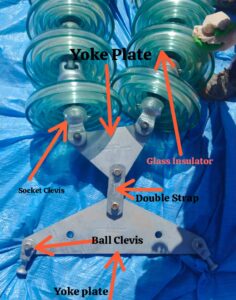
Below are some of the pictorial views of the hardware parts of the insulator assembly.
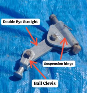 2) Hardware parts
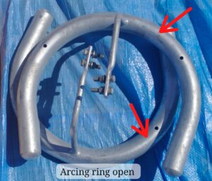
(It protect insulator strings from being destroyed by the free burning arcs caused by lightening faults.)
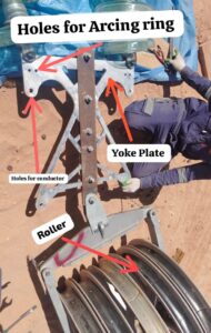
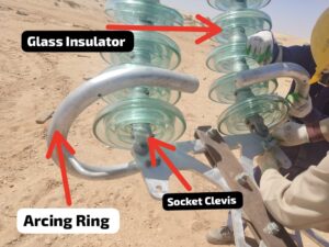
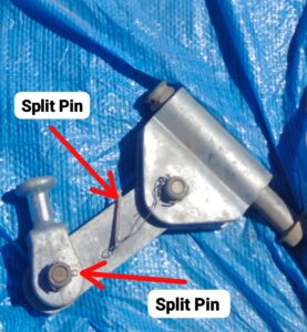
These hardware fittings are fitted with the assembly strictly as per the drawing, keeping the bolts positioning in view, ensuring the proper insertion of split pins and once final inspection by the site foreman or the Site Engineer ensuring the complete assembly as per the drawings and consultant site requirements.
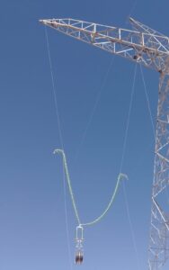
It should be noted that the insulator assembly structure differs for HVAC & HVDC lines. In the below image, the HVDC insulator has been shown and named as “DC Suspension Set”.
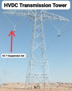
In conclusion to this article, insulator hoisting is very prime and crucial activity in any over head transmission line. The tools required for this activity will differ in its ratings and capacity, and would be based on the voltage & nature of the line, HVAC or HVDC. Moreover, the mechanism and the standards would remain same.
Feel free to discuss any queries related to the topics or related to overhead lines.
